
Harmonic Drive CSF-2A and CSF-2A-LW Component Sets Review: Specs, Price and Applications

Updated: 4 days ago
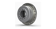
CSF-2A and CSF-2A-LW are cup-type strain-wave gearing component sets for integration into an OEM mechanism. The lightweight LW version reduces the gearing mass, while the customer supplies the housing, output support, motor and drive. The three-element reduction mechanism should be treated as part of a designed rotary axis, with alignment and lubrication requirements that a complete housed gear unit normally helps to contain.
Quick Verdict
Choose CSF-2A-LW when low moving mass and control over the surrounding structure justify designing the mechanical interfaces. Choose a complete gear unit when a supplied output-bearing arrangement and established mounting interfaces offer greater value. Compare the exact size and ratio; lightweight gearing does not establish the mass or stiffness of the completed joint.
Harmonic Drive CSF-2A and CSF-2A-LW Component Sets at a Glance
Specification | Details |
Mechanism | Wave generator, cup-shaped flexspline and circular spline |
Construction | Component set; customer-designed housing and machine-load support |
Lightweight offering | Current manufacturer page lists four sizes for CSF-2A-LW |
CSF-20-100-2A-GR | 40 Nm rated L10; 82 Nm repeated peak; 147 Nm momentary peak |
CSF-20-100-2A-GR-LW | Same listed 40 / 82 / 147 Nm torque entries for this exact size and ratio |
Size 20, ratio 100 mass | 0.28 kg standard component set; 0.14 kg LW component set |
Size 20, ratio 100 positioning entries | 1 arcmin standard accuracy; 4.5 Nm backdriving torque in current tables |
Torque terminology | Rated, repeated peak and momentary peak are separate limits |
Drive scope | No servomotor, controller or fieldbus included |
Price | Request a quote for exact component code and integration scope |
Design and Engineering Assessment
A standard CSF-20-100-2A-GR and its LW equivalent illustrate a useful comparison: both list 40 Nm rated torque, 82 Nm repeated peak and 147 Nm momentary peak, but their component masses are 0.28 kg and 0.14 kg respectively. The 50% reduction in this particular pair is stronger than the family’s broad 30+% lightweight statement. It is a configuration-specific comparison, not a promise that every LW size or complete axis will lose half its mass.
The mechanism contains the wave-generator bearing, but that bearing is not a supplied machine-load output bearing. Radial forces, axial forces and overturning moments at a gripper or turntable need an independently designed support path. Loading the flexspline as though it were an arbitrary structural bearing can compromise alignment, life and positioning behavior.
Zero backlash describes the gearing engagement. The assembly still has elastic torsional deflection, transmission error and supporting-structure compliance. A high-resolution motor encoder cannot measure every deflection between the reducer and the load. Define the required load-side accuracy under working torque, rather than using the zero-backlash phrase as an accuracy specification.
The ratio and mounting arrangement set motion direction and speed relationships. In a conventional fixed-circular-spline arrangement the flexspline output reverses relative to the wave-generator input. Alternative member constraints require their own kinematic calculation. The ratio printed on a component set does not authorize an arbitrary arrangement without checking the manufacturer’s design guidance.
Designing the Housing and Output Support
Lay out the motor shaft, wave-generator connection, circular-spline mounting and flexspline output before selecting bearings. Each interface needs suitable runout, concentricity and axial positioning. A lightweight reducer in a poorly controlled housing can produce a heavier final assembly once bearing support and corrective reinforcement are added.
Support the payload near its working load plane where practical. A long cantilever increases overturning moment and bearing deflection even when transmitted torque is modest. Check bolt preload, mounting-face flatness and bearing life together; reducer torque capacity alone does not establish acceptable cantilever length.
Standard CSF Versus the LW Version
Use the full ordering code to compare standard and lightweight drawings. The current size-20 ratio-100 tables show matching torque limits and standard accuracy, with different component mass. That evidence supports using LW in a mass-sensitive axis of this size; it does not establish identical mounting dimensions, temperature behavior or every other ratio’s overload capacity.
For a moving robot joint, reduced gearing mass can lower the demand on upstream axes. Include the required bearings, housing, motor, brake, cables and load attachment in the mass budget. The reduction in bare component mass is only one contribution to total moving inertia.
Sizing for the Actual Motion Profile
Calculate input speed from required output speed and the selected reduction ratio. Include motor acceleration and reflected load inertia. The motor must supply the load torque divided by the reduction ratio with appropriate efficiency and friction allowances; it must also accelerate its own rotor and the input-side parts.
Check the recurring acceleration and deceleration peaks against the repeated-peak limit. Reserve the momentary limit for the manufacturer-defined exceptional load case. Repeatedly planning normal operation near a momentary limit defeats the distinction between routine duty and short exceptional loading.
Lubrication, Assembly and Acceptance
Use the specified lubricant, quantity and orientation guidance for the selected size and installation. The component catalog identifies lubrication qualifications for larger sizes and some ratios; a grease statement from a small reducer cannot automatically be extended to the entire CSF range. Keep the approved instructions with the assembly drawing.
At acceptance, compare no-load running behavior, input current, temperature rise and output positioning before and after applying representative machine loads. Verify forward and reverse positioning at the load, including settling and temperature effects. These checks help separate drive tuning, housing misalignment and elastic deformation.
Selecting a Complete Gear Unit Instead
A housed CSF gear unit can simplify integration by supplying an established output support and mounting arrangement. The component set makes sense when the designer can use the surrounding machine structure efficiently or needs a custom packaging envelope. The decision is an engineering and manufacturing tradeoff, rather than a universal preference for fewer purchased parts.
Applications and Selection
Custom rotary joints, compact positioning mechanisms and mass-sensitive automation axes
For Harmonic Drive CSF-2A and CSF-2A-LW Component Sets, define the actual machine duty before selecting an ordering configuration. Include the required operating point, available installation space, environment and control interfaces. The specification table describes the product or family; the surrounding machine determines which of those features matters for the intended job.
Price and Value
Price: Request a quote for the exact configuration. Compare the product, compatible control equipment, required mechanical parts, cabling and commissioning as one installed system. A component price alone does not represent the cost of a working automation axis.
Evaluate an alternative against the same duty and acceptance criteria. Match the continuous operating requirement first, then compare transient capability, feedback, mechanical fit and support. This avoids choosing between superficially similar products whose ratings describe different operating conditions.
Pros and Cons
Advantages
A directly integrated component set gives OEMs control over joint packaging
The verified size-20 ratio-100 LW example halves gearing mass while retaining the listed torque limits
Zero-backlash reduction supports precise reversing motion when the complete axis is properly designed
Limitations
Customer must engineer housing, alignment, output support and lubrication
Zero backlash does not eliminate torsional deflection or load-side positioning error
Bare component savings do not describe complete-axis mass or cost
Who Should Consider Harmonic Drive CSF-2A and CSF-2A-LW Component Sets?
OEM motion-axis designers integrating a motor, reduction stage and machine load
Harmonic Drive CSF-2A and CSF-2A-LW Component Sets FAQ
Is CSF-2A-LW a complete servo actuator?
No. It is a lightweight gearing component set. The OEM supplies the motor, drive, housing, output support and associated machine interfaces.
Does the component set include an output cross-roller bearing?
Do not assume that it does. The wave generator includes a bearing within the reduction mechanism, while the machine load requires an appropriately designed output support arrangement.
How much lighter is the LW version?
The manufacturer describes the LW family as more than 30% lighter than standard CSF components. For the exact CSF-20-100 pair, current tables list 0.14 kg for LW and 0.28 kg for standard. Other configurations require their own comparison.
Does LW mean reduced torque in every size?
No universal reduction should be assumed. The verified CSF-20-100 standard and LW entries both list 40 Nm rated L10, 82 Nm repeated peak and 147 Nm momentary peak. Confirm the exact selected code.
Does zero backlash guarantee one-arcminute positioning?
No. Backlash, transmission accuracy, repeatability and elastic deflection describe different effects. The size-20 ratio-100 table lists 1 arcmin standard accuracy; actual load positioning also depends on the integrated mechanism and operating conditions.
Can a motor encoder measure all output deflection?
No. Motor feedback measures the input-side rotation. Deflection in gearing, bearings, housing or load attachment can occur downstream; demanding axes may require separate load-side measurement.
Can the momentary torque rating be used for every acceleration?
Routine recurring accelerations should be checked against the repeated-peak and duty limits. The momentary limit applies to the manufacturer-defined exceptional event and is not a continuous operating rating.
What should an OEM request with a quotation?
Request the exact size, ratio, standard or LW code, current drawings, lubrication instructions, mounting requirements and an application review covering load support, speed and duty. Include the motor and housing design boundaries.
Prices are indicative and may change. Confirm the final configuration, commercial terms and delivery schedule before ordering.


